Please see Electricity Class 10 Science Revision Notes provided below. These revision notes have been prepared as per the latest syllabus and books for Class 10 Science issues by CBSE, NCERT, and KVS. Students should revise these notes for Chapter 12 Electricity daily and also prior to examinations for understanding all topics and to get better marks in exams. We have provided Class 10 Science Notes for all chapters on our website.
Chapter 12 Electricity Class 10 Science Revision Notes
Electric Potential
So, by now you must have understood electric potential and potential difference.
Let us define these two for you −
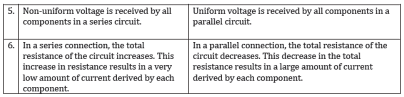
Electric potential of a point in an electric field is defined as the work to be done to move a unit positive charge from infinity to that point.
Potential difference between two given points in an electric field is defined as the amount of work to be done to move a unit positive charge from one point to the other.
A chemical reaction within a cell develops a difference in potential between both its terminals. When a cell is connected to a circuit, the potential difference causes the charge to flow and hence, the current is flowing through the circuit.
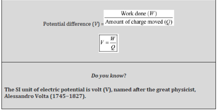
If we substitute the SI units of work done [i.e., Joule (J)] and charge [i.e., coulomb (C)] in the following relation, we get
V = W/Q
⇒ 1 V = 1J/1C
Hence, we can define potential difference between two points as 1 J of work that is required to move 1 C of charge between two points.
The potential difference between two points is measured with the help of a voltmeter. For this purpose, it is connected across the points from where the potential is to be measured
Do you know?
We can get an electric shock if we touch a naked live wire.

Electric current tends to flow due to the potential difference that exists between the Earth and a wire (as the wire acquires a positive value). Therefore, when we touch a naked live wire, our body provides the current a bridge or link to flow from high potential (wire) to zero potential (Earth) via our body. This flow results in an electric shock, which can prove to be fatal.
Do you know?
Birds sitting on live wires do not get electrocuted.
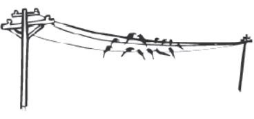
Potential difference is a must for current to flow. Birds do not get electrocuted while sitting on live transmission wires because their bodies do not provide a bridge or link for the electrons to flow. The potential of a bird’s body is zero before coming in touch with a wire. When a bird sits on a wire, its body potential rises and becomes equal to the potential of the wire. If a person standing on the ground touches the bird, then both will get an electric shock. This is because the person’s body would provide a link for the electrons to pass on to the Earth.
Electric Current
Electricity requires a link to flow from cells. Do you know how electricity flows through an electrical circuit? What constitutes a current in the circuit?
Electric charge
The distribution of charge in a body is measured in coulombs. The quantization of charge requires that a charge on a body always remain the integral multiple of charges in an electron. Therefore, we have the relation.
Q = ne
Where, Q is the charge on the body
n is the number of electrons
e is the charge on electrons (1.6 × 10⁻¹⁹)
The SI unit of electric charge is coulomb, denoted by the letter ‘C’.
Number of electrons in 1 C of charge
Total charge possessed by one electron = 1.6 × 10⁻¹⁹ C
i.e., 1 electron = 1.6 × 10⁻¹⁹ C
⇒ 1 C = 1/1.6×10-19 electrons
Or, 1 C = 6.25 × 10¹⁸ electrons
Hence, we can say that one coulomb of electric charge contains 6.25 × 10¹⁸ electrons.
Electric current (Flow of charges)
The directed flow of negative charges (i.e. electrons) through a wire is called an electric current. A current is said to be flowing if a closed link has been provided for the electrons. This link is called the electric circuit. An electric circuit provides a continuous path for the electrons to flow, and hence constitute an electric current.
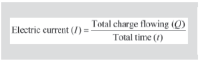
The magnitude of an electric current is defined as the amount of electrons passing through a cross-sectional area of the wire within a given interval of time.
i.e., Current =

Or, I = Q/t
Where, I → amount of current
Q → amount of electrons flowing through a cross-section
t → time taken
The SI unit of current (I) is taken as ampere (A), named after the great physicist, Andre Marie Ampere (1775 − 1836).
Since, the SI unit of charge is coulomb (C) and that of time is second (s), we define 1 ampere (A) as,
1 A = 1 C/1 s
i.e., 1 ampere is 1 coulomb of charge flowing through a conductor in one second.
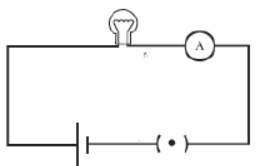
An Ammeter is used to measure the amount of current flowing in a circuit. The ammeter is always connected besides the electric components of a circuit.
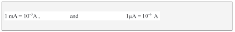
The smaller units of current are expressed in millliampere (mA) and micro ampere (μA).
The relation between them is given by:
Direction of the electric current
It is well known that current is the flow of negatively charged particles i.e. electrons. Since like charges repel each other and unlike charges attract each other, the negative terminal of the cell pushes the electrons, and the positive terminal attracts them. Hence, the electrons flow from the negative terminal of the battery to the positive terminal via the electric components such as the bulb placed between them.

Conventionally, the direction of an electric current is taken as opposite to the direction of an electric charge. Hence, electric current flows from the positive terminal to the negative terminal via the bulb.
What makes the electrons, and hence the current to flow in a circuit?
It is the difference in potential that tends to push the electrons across the circuit, which in turn is responsible for the flow of current.
You know that potential difference between two points can be compared with the difference between the water levels in two connected containers.
In the same way, the flow of electric current can be compared with the flow of water between the water columns. Water always flows from higher level to lower level. Similarly, electric current always flows from high potential to low potential.
Do you know how the flow of electric current occurs?
The answer is very simple. The flow of electric current occurs because of the flow of charged particles. In metallic conductors, the charged particles are electrons. Therefore, we can say that the flow of electric current is nothing but a flow of electrons.
The Direction of Electric Current
By convention, we consider the direction of electric current to be the same as the direction of flow of positively charged particles. As electric current in a conductor is the flow of electrons, which are negatively charged particles, the direction of flow of current is opposite to the direction of flow of electrons.
Amount of Electric Current
By now, we know that electric current is the flow of charged particles in a conductor.
Therefore, the amount of current is also related to the amount of charge. The amount of electric current in a conductor is the flow of total charge per unit time.
The unit of electric current is ampere (A). It is defined as the flow of one coulomb of charge in one second.
That is, 1 A = 1 C/1 s
Ohm’s Law

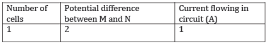
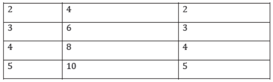
Construct a simple electric circuit using a battery having 5 cells of equal potential V, a resistor of resistance R, and a switch. Connect a voltmeter and an ammeter across and along the resistor respectively (as shown in the given figure). Make sure that initially the circuit is connected with only one cell. Now, switch on the circuit and measure the readings in both the ammeter and the voltmeter. Note these readings in the table given below.
Now, connect the circuit with two cells and measure the readings in the voltmeter and the ammeter. Repeat the process using three, four, and five cells respectively and note the readings in each case. An example is tabulated below.
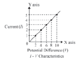
Now, plot a graph between the potential difference and the current for these five readings. Draw the potential difference on x-axis and current on y- axis. You will observe that the graph between the two quantities comes out to be a straight line. What is the significance of this straight line?
You know that current is a flow of electric charge. These charges flow from one point to another when a potential difference exists between the two points. How do we relate potential difference with current?
If you calculate the ratio V/I for all five cases, then you will get the same value approximately. This implies that the ratio V/I is constant. It does not depend on the number of cells used in the circuit. Hence, we can say that the potential difference (V) is directly proportional to current (I). Thus, V∝I
This relation is known as Ohm’s law.
According to this law, under constant physical condition i.e. constant temperature, pressure etc. the applied potential difference is directly proportional to the current flowing in the circuit.
Or, V = RI
Where R is a constant of proportionality called resistance of the resistor, it tends to resist the flow of charge through a conducting wire. Its SI unit is Ohm (Ω).
Thus, we can write Ohm’s law as
I = V/R
Hence, according to Ohm’s law, current is
- Directly proportional to potential difference.
- Inversely proportional to resistance.
If the potential difference is doubled (keeping resistance the same), current will also get doubled. On the other hand, if resistance is doubled (keeping potential difference the same), current will reduce to half.
Ohmic resistors:
Conductors which follow the ohm’s law at constant temperature are called ohmic resistors.
Examples: All metallic conductors (Copper, Aluminium, silver etc.), copper sulphate solution with copper electrodes, and dilute sulphuric acid, etc.
A straight line graph passing through the origin is obtained between potential difference V and current I for such resistors. This means that the ratio of V and I i.e. R is constant for all values of V or I.
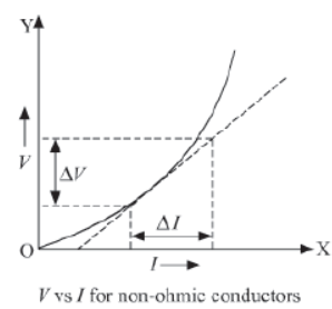
Non-ohmic resistors:
Conductors which do not follow the ohm’s law are called non-ohmic resistors. Examples: LED, solar cell, junction diode, transistor, bulb filament etc.
A non-linear graph is obtained between potential difference V and current I for such resistors. This means the ratio of V and I i.e. R does not remains constant for such resistors.
Example:
In an electrical circuit,what is the resistance offered by a bulb to a flow of charge if the ammeter and the voltmeter show a reading of 2 A and 12 V respectively?
Solution:
Given that,
Potential difference, V = 12 V
And current, I = 2 A
According to Ohm’s law, potential difference
V = IR
Or, R = V/I
∴ R = 12V/2A = 6 Ω
Hence, 6 Ω resistance is offered by the bulb to the flowing charge.
Example:
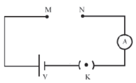
In the given electric circuit, the potential of the battery is 24 V.

When a copper wire is connected between points M and N, the ammeter reads 5 A, whereas when a chromium wire of the same length and thickness is connected between points M and N, the ammeter reads 2 A. Can you tell which wire offers greater resistance to the flow of charges?
Solution:
Given that,
potential difference for both the wires, V = 24 V
For Copper wire:
Current, I = 5 A
On applying Ohm’s law, we get
⇒ V = IR
Or, R = V/I
∴ Rcu = 24V /5A = 4.8 Ω
For Chromium wire:
Current, I = 2 A
On applying Ohm’s law, we get
V = IR
Or, R = V/I
∴ Rcr = 24V/2A = 12 Ω
Since, Rcr is greater than Rcu, chromium wire will offer greater resistance in comparison to copper wire. Hence, Ohm’s law shows that chromium wire is a poor conductor of electricity as compared to copper wire.
Factors Affecting Resistance of a Conductor
Do you know why it is advisable to use thick conducting wires in wiring?
This is related to the amount of resistance offered by wires used in circuits. We know that resistance is a natural tendency of the conductors to oppose the flow of electric charge from it. Hence, it causes a loss of electricity and should be minimised. This can be achieved by using thick conducting wires.
Here, we will discuss the different factors on which resistance of a conductor depends.
Factors that affect resistance
Construct an open circuit with open ends M and N (as shown in the figure). Take six pieces
Case (i) Copper wire → of length MN of the given cross-section.
Case (ii) Copper wire → of length greater than MN having the same cross-section.
Case (iii) Copper wire → of length less than MN having the same cross section.
Case (iv) Copper wire → of length MN but a comparatively thicker cross-section.
Case (v) Copper wire → of length MN but comparatively a thinner cross-section.
Case (vi) Chromium wire → of length MN and of same cross-section as in case (i).of wire with dimensions as given below.
Connect copper wire of case (i) between the open points M and N, and note the readings in the ammeter. The reading will give you the amount of current flowing through the copper wire.
Similarly, connect wire of case (ii) and note the reading in the ammeter. Repeat the process with the remaining four wires and make a table of your readings in each case. Scrutinize the readings and compare them with the dimensions of the wire. Does the current depend on the length, cross-section, and nature of the material used?
You will notice that the amount of current that flows through wire in case (i) is greater than that flowing through wire in case (ii). What does this mean? This means that a long wire offers greater resistance in comparison to a short wire. Also, resistance decreases with an increase in the cross-sectional area. Similarly, if you allow the current to flow in each wire for a relatively longer period, you will find that there is a decrease in current. Hence, from this activity we can say that resistance of a conductor depends on the following:
I. Length of the conductor
II. Cross-sectional area of the conductor
III. Temperature of the conductor
IV. Nature of the material used
Symbol of resistor

I. length of the wire
Resistance is directly proportional to the length of the conductor i.e.

Where, l → length of the conductor
II. Cross-section of the conductor
Resistance is inversely proportional to the area of cross-section of the conductor i.e.

A → area of cross-section
- Since conductors have a circular cross-section, the area of cross-section is directly proportional to the square of the radius of the cross-section i.e.
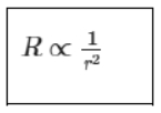
r → radius of the cross-section
When the diameter of a conductor is made double, its resistance becomes one fourth.
Thus, we can write,
R ∝ l/A
Or,

Where, is the proportionality constant, called the electrical resistivity of the material of the conductor. It is also known as specific resistance.
The resistivity or specific resistance of a substance is equal to its resistance, if it has a unit length and unit cross-sectional area.
The SI unit of resistivity is Ω m (Ohm-meter).
Resistivity is the characteristic property of a material. It only depends on the nature of the material and not its dimensions. This is one of the major differences between resistance and resistivity. But like resistance, resistivity also varies with temperature.
Conductivity
The reciprocal of resistivity is known as conductivity. Its SI unit is
Rheostat or variable resistance:
It is a device used in an electric circuit by which we can continously change the resistance of the circuit. It does this by varying the length of the resistance wire used in circuit.
Graphic

Resistance box
It is a box consisting of several resistances of different values connected in series. As per the circuit requirement, resistance of any desired value can be achieved by removing or inserting the key from the box.

III Temperature of the conductor
Experimentally, it is found that resistance of a conductor increases with the temperature and vice-versa. But resistance of alloys such as nichrome, constantan etc. is only slightly affected by temperature. Hence, alloys are better suited in electrical circuits.
Semiconductors
Germanium and silicon offer resistance lying between the resistances of conductors and insulators. Hence, these are called semiconductors. Their resistivity decreases with temperature, in contrast to conductors and alloys. Semiconductors have great importance because their conducting properties change with temperature, impurity, concentration etc.
IV Nature of the material
In the above activity, you will notice that the reading in the ammeter for wire in case (i) is greater than the reading for wire in case (vi). This means that a copper wire offers less resistance than a chromium wire of the same length and cross-sectional area, on the nature of the material used. Hence, it can be deduced that the resistance of a conductor depends on the nature of the material used.
The following table shows the resistivity of some materials at 20 °C.


Interesting Fact:
Superconductivity
The phenomenon of superconductivity was discovered by K. Onnes in 1911. He discovered that the resistance of mercury fell abruptly to zero on lowering its temperature below 4.2 K. This means that if a current is passed through a superconducting wire it will continue to flow forever!
Series and Parallel Circuits
On entering his reading room, Rakesh switches on the bulb and finds that the bulb does not glow because it has got fused. Then, he turns on his night bulb and is surprised to see the bulb glow. He remembers reading in his science book that current cannot flow through an open circuit. Since the filament of the bulb is broken, current can not flow through the entire circuit of the room. Then, what makes the night bulb glow even when the fused bulb causes an open circuit?
This happens because the bulb and the night bulb are connected in parallel combination with each other, rather than in series. A parallel connection ensures a continuous flow of current through the night bulb.
To get the desired quantity of current, resistors are connected in series or in a parallel combination. For example, resistors used in radios, televisions, and other electronic devices are connected in series as well as in parallel combinations.
In this section, we will learn about the different combination of resistors in a circuit and the effects of such combinations in current and potential differences.
System of resistors
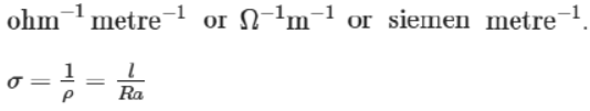
1. Series combination
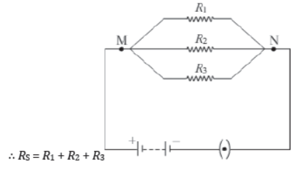
In a series connection, all resistors are connected end to end (lengthwise) with each other. In such connections, the total resistance of the circuit increases. The given figure shows three resistors of resistance R1, R2, and R3 respectively connected in a series with each other.
The equivalent resistance of the resistors connected in series is given by the algebraic sum of their individual resistances.
∴ Equivalent resistance or RS = R1 + R2 + R3 + …
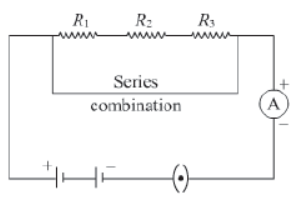
Take three resistors of resistances 2Ω, 4Ω, and 6Ω respectively. Construct a simple electric circuit by joining them in series with a 12 V battery (as shown in the given figure). Now, note the readings in the ammeter after turning the switch on. Repeat the process by connecting the ammeter anywhere in the circuit. You will observe that the ammeter will read the same reading at any point in the circuit. Why does this happen?
This happens because an equal amount of current flows in each component of a series circuit. There is no current division in the series combination of resistors. Hence, in a series circuit, current remains constant through out the circuit.
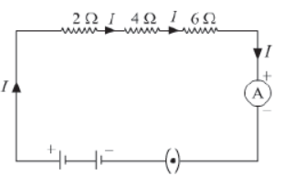
Now, using a voltmeter, take readings by connecting its two terminals at point AB, BC, CD, and AD respectively. Let these readings be V1, V2, V3, and V respectively. In each case, you will observe different values of voltage. Why does this happen?
If you add voltages V1, V2, and V3 and compare it with V, you will find that the applied voltage V is equal to the algebraic sum of the divided voltages V1, V2, and V3 respectively.
Thus,
V = V1 + V2 + V3
Division of voltage occurs in a series circuit.
Magnitude of these divided voltages is given by using Ohm’s law for resistors R1, R2, and R3 respectively. Since an equal amount of current flows through each resistor, we get
V1 = IR1
V2 = IR2
V3 = IR3
For each resistor, we have Ohm’s law as
V = IR
Or, V1 + V2 + V3 = IR
Or, IR1 + IR2 + IR3 = IR
Or I(R1 + R2 + R3) = IR
Here, RS is the equivalent resistance of all three resistors, when they are connected in a series. Note that when any one resistor is removed from a series circuit, the circuit becomes an open circuit. As a result, the flow of current stops and other resistances also stop working.
2. Parallel combination
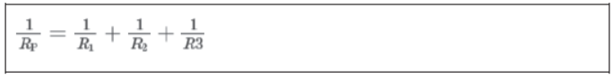
In a parallel connection, all resistors are connected sideways with each other. In such a connection, the total resistance of the circuit decreases. Thegiven figure shows parallel combination of three resistors of resistances R1, R2, and R3 connected between points M and N.
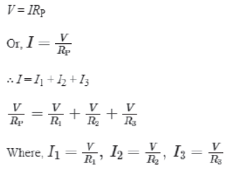
In this case, equivalent resistance (RP) is given as

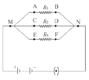
Take three resistors R1, R2, and R3 of different resistances and construct a parallel circuit using these resistors (as shown in the given figure). Now, with the help of a voltmeter, measure the potential differences between points M and N, A and B, C and D, E and F respectively. You will observe that the voltmeter shows the same reading in each case. Why does this happen?
This happens because supplied voltage does not divide across resistors in a parallel circuit.
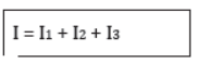
From your readings, you will observe that total current (I) is equal to the sum of divided currents I1, I2, and I3. Thus,
Applying Ohm’s law at each resistor,
Note that when any one resistor is removed from a parallel circuit, other components of the circuit remain working because the remaining current flows through other resistors.
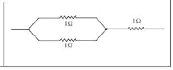
Three resistors are connected to each other (as shown in the figure). Can you find the equivalent resistance?
Domestic wiring and decoration
Domestic wiring in a house requires a number of electric devices to run simultaneously.
Thus, they should be independent of each other i.e. the working of one device should not depend on the working of another device.
For example, the working of a fan should not be affected when a bulb in the room gets fused. In parallel circuits, if one appliance stops working, all other appliances work as usual. Hence, parallel circuiting is used in house wiring or in lights used to decorate buildings on occasions. This is done to ensure that if one bulb fuses, the others remain functioning.
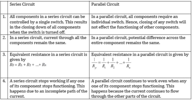
The differences between series and parallel circuits can be summarised in the form of the following table:
Heating Effect of Current
It is winter time. Dilip and his younger sister Meenakshi are studying in their room. A room heater has been kept to keep the temperature of the room above normal. This helps them bear the cold. Dilip has read in his science book that electricity is required for operating any electrical device. He wonders how a room heater can emit a large amount of heat.

The heater emits heat due to the conversion of electrical energy into heat energy. This phenomenon is known as the heating effect of current. Let us learn more about this effect.
A wire (say nichrome wire) becomes hot when electric current is allowed to flow through it for a relatively long time. This phenomenon is known as the heating effect of electric current.
Joule’s Heating
We know that current begins to flow through a wire when it is connected with a source. All wires offer some resistance to the flow of current. To maintain a uniform supply of current, the source must expend its energy (because of which the source eventually gets exhausted). Part of this energy is used for maintaining the supply of current, while the rest is dissipated in the form of heat. This dissipated heat is responsible for the heating of the wire.
The heating effect is more prominent in wires of high resistance. For example, if we take nichrome and aluminium wires of equal length and cross sectional area, and pass an equal amount of current for the same time, we will observe that the nichrome wire gets more heated than the aluminium wire. This happens because nichrome offers more resistance to the flow of current than aluminium.
When a current (I) flows through a resistor of resistance (R) for time (t), the amount of heat produced (H) is given by
H = I2Rt
This is called Joule’s law of heating. This law suggests that the heat produced in a resistor is directly proportional to the
1. square of the current flowing through the resistor, i.e., H ∝ I2
2. resistance of the resistor, i.e., H ∝ R
3. time for which the current flows through the resistor, i.e., H ∝ t
Thus, we can infer from Joule’s heating effect that an appliance offering more resistance to the flow of electrons releases more heat per unit time, keeping the potential of the source
constant.
The Joule’s law of heating can have other forms as
H = (V2/R)t and H = VIT
Example: A room heater can offer a maximum resistance of 100 Ω when 5 A current flows through it for one minute. What is the maximum amount of heat produced by the heater?
Solution:
Current, I = 5 A
Maximum resistance, R = 100 Ω
Time, t = 1 min
= 60 s
Using Joule’s law of heating, the heat produced is given as H = I2Rt
∴ H = (5)2 × 100 × 60
= 150000 J
Hence, the room heater will produce a maximum of 150000 J of heat in one minute.
The heating effect of current is used in various heating appliances such as electric irons, room heaters, water heaters, hair dryers, geysers, etc. In all these devices, electrical energy is converted into heat energy, which is governed by Joule’s heating effect.
Let us learn about the functions of some heating devices.
1. Electric heater
An electric heater consists of a long coil of wire arranged on an insulating sheet, as shown in the given figure. When electric current is allowed to flow through this coil, it turns red hot because of the heating effect of current. As a result, it provides a specific amount of heat, which can be used for different purposes.

2. Electric Iron
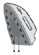
An electric iron consists of a thin metal plate that gets heated when electric current flows through it. This, in turn, heats the thick iron base of the device.
3. Water heater
An electric water heater consists of a coil of wire that gets heated when electric current flows through it. This, in turn, heats the water in which the heater is completely immersed.
Do You Know?
Edison and his bulb
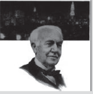
Thomas Alva Edison (1847−1931) was one of the greatest inventors in the history of science. He had one thousand inventions to his name besides the electric bulb. The bulb invented by him was comparatively long-lasting because he used a filament made of a metal having a high melting point. Now-a-days, tungsten filament is used in the electric bulb because it does not melt easily.
4. Electric bulb
A bulb consists of a filament that radiates heat and light when current flows through it. The filament of a bulb is made of tungsten coil. The flow of current causes the filament of the bulb to heat up to an extremely high temperature such that it starts emitting light.

Caution: Do not touch heating devices directly because they can cause your fingers to burn severely.
All heating devices draw a large quantity of electricity to heat the respective appliances. However, bulbs are designed to emit light only. Hence, there is wastage of electricity in the form of heat. This wastage of electricity is reduced by replacing these electric bulbs by compact fluorescent lamps (CFLs). A CFL is shown in the given figure.

List some heating devices that are being used in your home.
Until now, we have discussed the uses of the heating effect of current in situations in which it is allowed to flow through special devices. However, what happens if a large amount of current suddenly flows through a normal wire?
In such an unfavourable situation, the wire becomes hot and eventually melts down. This can cause serious damage to the different circuit components connected to it. In order to avoid such a situation, a fuse element is joined along with the circuit.
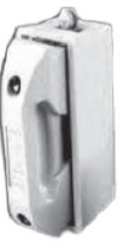
5.Electric fuse
Electric fuses are devices used for the protection of expensive electric devices such as bulbs, TVs, fans, etc. A fuse element has a very low melting point. Hence, it melts quickly whenever there is a slight increase in the amount of current. As a result, the path of the current is broken. This protects the device from being damaged by the abrupt flow of current. The given figure shows a simple electric fuse that is commonly used in households.
Electric Power and Energy
We use electricity to run various electrical appliances such as bulbs, tube lights, refrigerators, electric heaters etc. in our homes. Do you think all these home appliances consume an equal amount of electricity at a given time?
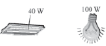
No, the amount of electricity consumed by an electrical appliance depends on the power rated on that appliance. For example, for 220 V potential supply, a tube light of rated power 40 W draws 0.18 A of current, whereas a bulb of rated power 100 W draws 0.45 A of current.
How can you determine the rate of consumption of energy by a given appliance?
Electric power
Electric power is defined as the rate of consumption of energy or simply the rate of doing work.
i.e., power (P) = work done (W) /Time(f) ……(i)
The work done by current (I) when it flows in a potential (V) for time (t) can be given by
W = VIt …………………. (ii)
⇒ Power, (P) = Vlt /t = VI
∴ Electric power or P = VI
The SI unit of power is watts (W).
Also, the energy dissipated or consumed by an electric appliance per unit time is given by
It is also an equation for electric power.
i.e., P = I2R
Now, according to Ohm’s law
⇒ V = IR
⇒I = V/R
If we substitute the value of I in the equation of power, we get
Hence, we get the expression for electric power as
Where, 1 W = 1 V × 1 A = 1 V A
1 watt is defined as the power consumed by an electrical circuit that carries a current of 1 ampere, when it is operated at a potential difference of 1 volt.
- Since Watt is a very small unit, we define a larger unit of power as kilowatt (kW). Thus,
1 kW = 1000 W
For practical purposes, we define kilowatt hour (kWh) as ‘unit’ where,
1 unit = 1 kWh = 1000 W × 1 hour
= 1000 W × 3600 s
= 36 × 105 Ws
= 3.6 × 10⁶ J
1 kWh is also the commercial unit of electric energy.
Note that electricity is a flow of electrons and nothing else. Hence, power stations only make the electrons flow through conducting wires for which they charge us. They do not create or generate the electrons.
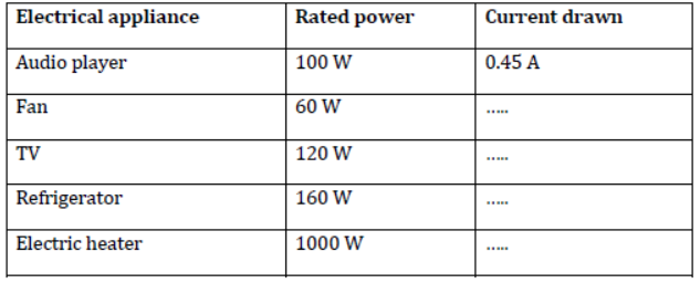
Prepare a list of electrical appliances commonly used in homes. Note down the respective watts rated on them. Now, try to calculate the amount of current drawn by respective appliances for a constant voltage of 220 V. Complete the table and discuss the result with your friends.
Example:
(i) The amount of current drawn by an immersion water heater is 6.8 A. If the heater is operated on 200 V of potential difference, calculate its power.
Solution:
Given that,
Potential difference, V = 200 V
Current drawn, I = 6.8 A
By definition of electric power, we know that
P = VI
Hence, P = 200 V × 6.8 A
= 1360 W
Hence, power of the given immersion heater is 1360 W.
Hence, power of the given immersion heater is 1360 W.
(ii) What is the monthly cost of energy to operate the given immersion water heater 3 hours/day at Rs 5.00 per unit?
Solution:
Power of the heater is 1360 W.
Energy consumed by it per day = 1360 W × 3 hours /1 day
Hence, energy consumed by it in 30 days = 1360 W × 3 hours/1 day x 30days
= 122400 W
= 122.4 kWh
= 122.4 units
Now, the cost of energy for one unit is Rs 5.00
Hence, the monthly cost of energy of the heater is Rs 612.
What is the amount of energy consumed by the given water heater in one month?